Originally published on fastradius.com on February 14, 2022
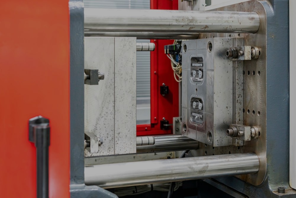
Many companies turn to injection molding services to cost-effectively produce a high volume of identical parts. Plastic injection molding involves melting thermoplastics in a heated barrel before injecting the molten material into a durable, precise metal mold via a pressurized nozzle. Once the material has cooled and hardened, the part is ejected, and the process is repeated. Companies use this manufacturing process to produce everything from electronics housings to water bottles.
Injection molding is a complex process, and one mistake can cause cosmetic flaws, compromise product integrity, and lead to expensive redesigns. The good news is most of these problems are avoidable as long as you follow design best practices. Here are 4 of the most common mistakes you need to watch out for as you design a part for injection molding.
An undercut is any recessed surface, protrusion, groove, overhang, thread, snap-fit, or other feature that prevents a part’s ejection from its mold. Undercuts can result in increased manufacturing costs, part complexity, and mold maintenance requirements, so it’s best to eliminate any potential undercuts whenever possible.
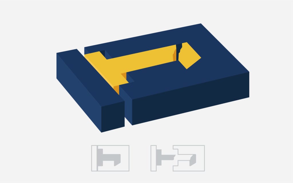
If you have an undercut that’s essential to your part’s design, there are a few ways to improve part ejection. Reorienting problematic features so that they’re parallel to the draw line is a cost-effective solution. This allows the part to eject without sustaining damage, eliminating the undercut. If you have parts with internal undercuts or faces without draft angles, you can also use lifters to ease the ejection process. You may be able to form undercut features by clever design of holes and slots in the part, which our Fast Radius engineers can help guide you through.
Having uniform wall thickness helps molten plastic flow through the mold cavity in a single direction, allowing the material to fill the cavity more precisely. However, since thinner walls cool faster than thicker walls, variations in wall thickness can cause sink, warp, short shots, and more.
To avoid these problems and ensure all areas of your part cool at the same rate, use consistent wall thicknesses. Wall thicknesses between 1.2mm and 3mm are best in most cases. If you must have walls of varying thicknesses, you should:
Adding draft, a slight taper to each vertical surface of the part, is essential for a smooth ejection. A part designed without draft may stick to the mold, and a lack of draft can also cause unsightly drag lines if the part’s vertical walls scrape against the metal mold during ejection. By adding a gentle taper, you can protect your part against friction, ensure a uniform finish, and reduce wear, tear, and warping during ejection.
Draft angle degrees depend on several factors, from wall thickness to surface texture. You’ll need to consider the material’s shrink rate, the part’s end-use function, and the depth of draw to determine the right draft angle, so it’s best to connect with an experienced manufacturing partner to get an accurate assessment. As a general rule, you should use at least 1.5 to 2 degrees of draft and add 1 degree for each inch of cavity depth. If your part has a heavily textured surface, you may need 5-degree draft angles to prevent drag lines.
Not only do sharp edges and corners require more pressure to fill, but they often cause parts to stick to the mold during ejection. Since sharp corners also make it more difficult for shots to flow through molds, they can result in vacuum voids, or areas where air bubbles become trapped. These can cause cosmetic damage, increase stress concentration, and result in part failure, so it’s important to round out your internal and external edges and corners whenever possible.
When designing corners, remember to model your corners to have consistent wall thickness. That means internal corners are filleted to 50% of wall thickness and external corners are 150%.
Injection molding design mistakes can set production back weeks, increase costs, and result in sub-par or even unusable parts. Taking the time to make thoughtful design decisions at the beginning of your project is essential and will save you time and money in the long run. However, there’s a lot to keep in mind, so working with an experienced injection molding partner like SyBridge can help you get the design right the first time.
When you partner with SyBridge, you’ll gain access to our team of engineers, advisors, and design experts who can help you through the entire manufacturing process. Whether you need help subtly incorporating draft into your design or deciding on an appropriate wall thickness, SyBridge can help you design the best possible part. Contact us today to get started on the design for your next injection molding project.
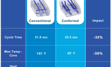
Forget typical cycle times. We're pushing the boundaries of conformal cooling. While traditional approaches deliver…
Forget typical cycle times. We're pushing the boundaries of conformal cooling. While traditional approaches deliver…
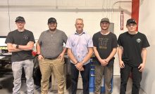
From left to right: Brayden Janak (apprentice); Logan Vifaquain (CNC machining, Programming and CMM); Ron…
SyBridge Technologies is proud to announce we have been awarded the 2023 General Motors Supplier…
Today, designers and engineers are accustomed to working with digital tools in their day-to-day jobs.…
Optimizing Your Injection Molding Process for Cost-Effective Manufacturing Excellence In today’s competitive landscape, manufacturers are…