
Originally published on fastradius.com on January 31, 2022
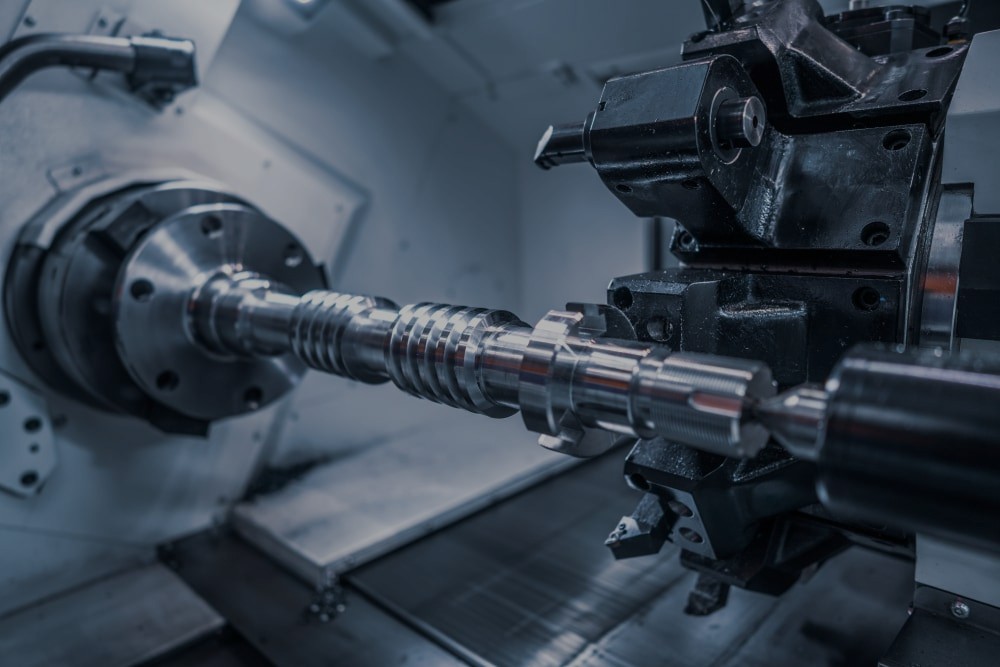
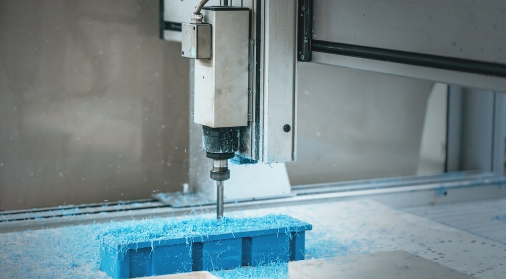
Computer numerical control (CNC) machining is a popular choice among manufacturers today, and it’s easy to see why. Not only is CNC machining compatible with a wide range of plastics and metals, but it’s also a reliable manufacturing process capable of producing precise and durable parts. Computer-programmed cutting tools remove material from a solid block to reveal a final product that meets your exact specifications, each and every time. However, if you’re not implementing CNC design best practices, you might find production times and costs creeping higher and higher.


At SyBridge, our team has spent years guiding product teams through the CNC machining process, so we know which pitfalls to look out for. Here are the four most common mistakes we’ve seen designers make when designing for CNC and how to solve them.
Since CNC bits are round, achieving sharp internal angles is expensive and time-consuming. Machining a 90° angle with a round bit is impossible because a round tool will always create a corner radius when milling an internal vertical edge, preventing parts from fitting together properly or causing end mills to grind to a halt mid-process.
Designing rounded corners eliminates the sharp internal corner issue altogether, but if your design calls for internal angles, design them with radii and soften them by increasing the corner radii. Having corner radii with the same diameter as the cutter can cause chatter and excessive tool wear, while corner radii that are too small will necessitate your machinist using several smaller bits at lower speeds. Increasing your corner radii by as little as 0.005” will help you save money and prevent errors.
If you have a square male part, you can use dog-bone or t-bone fillets to ensure it will fit within a female cavity with slightly rounded internal corners. Just make sure to design the entry point for your dog-bone fillet 15-20% larger than your router bit’s diameter.
Some product teams might design their part with thin walls to minimize material usage, but this “solution” causes more problems than it solves. Too-thin walls can cause part failure and warp, and they can compromise surface finish and machining process accuracy in metals. Thin walls can also snap, bend, or chip during machining due to the machining forces behind CNC cutting tools and excessive vibrations.
The ideal wall thickness for your part varies depending on which material is being CNC machined. For example, a wall thickness of 0.8 mm is fine when CNC machining aluminum. However, 1.5mm is the ideal minimum wall thickness for plastics. Also, keep in mind that the taller your wall is, the thicker it will need to be to increase its rigidity. Consult an experienced CNC manufacturing partner to ensure your measurements are correct.
If your design requires tall, thin walls, try to maintain a width-to-height ratio of 3:1. You can also add a slight draft to accelerate machining and reduce the amount of leftover material.
While CNC mills can engrave or emboss text and symbols onto parts with a high level of precision, machining text can cost you. First, your machinist will have to use a separate cutting tool for the text. Then, you have to consider the amount of time — and, by extension, money — machining text will add to your project because the small end mills that cut text are relatively slow.
The good news is that if you need to have text on your part, you have a few options. If you need to machine text, opt for recessed text instead of raised text so the machine doesn’t have to remove material from across the part’s entire surface. You can also have your machinist add the text post-machining. Laser marking parts after they’ve been CNC-machined, for example, can save you time and money.
Milling tools have a finite length, and their length determines how deep you should make cavities. In most cases, milling tools are most efficient and accurate when milling cavities up to double or triple their diameter in depth. Milling cavities that are any deeper can extend lead times, cause tool deflection or fracture, or result in chatter and chip evacuation difficulty. They may even require more expensive specialist cutting tools.
It’s best to avoid designing parts with deep cavities altogether, but if your part needs a deep cavity, hole, or thread, you should decrease the cavity’s depth as much as possible. Also, keep the milling tool’s length in mind.
Making thoughtful design decisions can save you time and money in the long run, but it can be tricky. You’ll need to have a thorough understanding of your part, its function, the CNC manufacturing process, your materials, and more. If you need some help, work with an experienced CNC manufacturing partner like SyBridge.
With a team of design and engineering experts and the latest design and manufacturing technologies, SyBridge has everything you need to optimize your parts, striking the perfect balance between cost and accuracy. Contact us today to connect with our experts and get started.
Forget typical cycle times. We're pushing the boundaries of conformal cooling. While traditional approaches deliver…
Forget typical cycle times. We're pushing the boundaries of conformal cooling. While traditional approaches deliver…
From left to right: Brayden Janak (apprentice); Logan Vifaquain (CNC machining, Programming and CMM); Ron…
SyBridge Technologies is proud to announce we have been awarded the 2023 General Motors Supplier…
Today, designers and engineers are accustomed to working with digital tools in their day-to-day jobs.…
Optimizing Your Injection Molding Process for Cost-Effective Manufacturing Excellence In today’s competitive landscape, manufacturers are…