
Originally published on fastradius.com on October 26, 2020
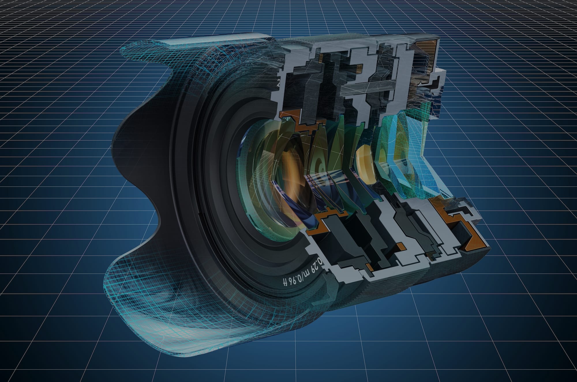
Computer-aided design, or CAD, modeling refers to the process of using virtual models to test and refine part design before physical production begins. 3D CAD models are identical to the final product in both dimensions and details, which can help engineers optimize parts for design and manufacturability in a cost-effective manner. 3D CAD models are utilized to additively manufacture prototypes, for instance, while 2D CAD models can be used to create photorealistic renderings and visualizations of parts and components.
CAD modeling tools can provide manufacturing teams with a number of benefits — such as increased productivity and more efficient design validation — but the software has traditionally required specialized training and years of on-the-ground experience to use effectively. Until recently, the majority of CAD software training materials targeted new users, leaving the specialists interested in developing their skills without the resources to do so.
While this has begun to change in recent years, the advantages that more advanced CAD modeling tools and techniques can provide are significant, and manufacturing teams would do well to incorporate them into production practices. Here’s what designers and product managers need to know.
Two key techniques for improving the efficiency and effectiveness of CAD modeling are master modeling and equation-driven design.
Master modeling — also known as top-down design or skeleton modeling — is the cleanest way of designing assemblies. This is because all of the components are linked parametrically: each assembly contains a master part, from which the child parts inherit their geometry, giving engineers a way to control downstream parts more easily.
Consider this example: If a designer needs to increase or decrease the size of a ballpoint pen or computer mouse, they’ll have to adjust each of the product’s components individually — a process that creates multiple opportunities for error. However, master modeling allows the designer to make changes to only the master part, which then automatically translates the changes to the other components within the assembly. This helps keep part models and components tidy, and radically improves the efficiency of design modifications.
Equation-driven design, on the other hand, is a technique that allows engineers to create and model part geometries that align with equation-based constraints or relationships within the part assembly. Many systems incorporate dynamic relationships and ratios that change in response to certain geometric features; equation-driven design provides a useful means of bridging geometry and part performance.
Dynamic fluid nozzles are one example of equation-driven design in practice. These nozzles modify their outlet diameter in response to changes in inlet diameter or pressure — in essence, the diameter or pressure values determine how the design can achieve the desired part performance.
In addition to the specific advantages of master modeling and equation-driven design, CAD modeling software provides a range of benefits to manufacturers. The precision of CAD models enables cleaner designs and fewer opportunities for error while making it easier for engineers to design what they actually have in mind — rather than being limited by skill or resources. CAD models are also easier to maintain and edit compared to the old paradigm of drafting drawings on paper, as they’re not subject to the wear and tear of their physical counterparts, and they can be easily understood when shared with other designers.
CAD modeling does have a few limitations, primary being the significant time and energy required to learn how to use the software effectively. Historically, there haven’t been many resources available for learning advanced CAD modeling techniques, and becoming familiar with the full range of the software’s capabilities required many hours of practice.
There are also very few “open source” resources available to teach these advanced functions, though some software companies, like Fusion360, have begun to provide tutorials in recent years. Another limitation is that traditional CAD systems typically cannot make organic shapes, forms, and textures. There is, however, a separate class of software designed for making organic, complex forms.
Ultimately, CAD modeling, while difficult and time-consuming to learn, helps designers and product managers in a number of key ways. 3D CAD models help make managing complex assemblies — some which may include hundreds of related parts — a much simpler process. They enable cleaner, more organized, and more comprehensible part design, which in turn, allows product teams to test and optimize components before production begins.
SyBridge is an on-demand digital manufacturing hub prepared to help product teams of any size or shape execute on their most ambitious projects. Our team of seasoned designers and engineers are schooled in the latest CAD modeling techniques and can leverage both cutting edge technologies and traditional manufacturing methods effectively to ensure that every part is created on-time, in accordance with key requirements, and at a competitive rate. Contact us today to learn more about how we can team up to create new possibilities.
Forget typical cycle times. We're pushing the boundaries of conformal cooling. While traditional approaches deliver…
Forget typical cycle times. We're pushing the boundaries of conformal cooling. While traditional approaches deliver…
From left to right: Brayden Janak (apprentice); Logan Vifaquain (CNC machining, Programming and CMM); Ron…
SyBridge Technologies is proud to announce we have been awarded the 2023 General Motors Supplier…
Today, designers and engineers are accustomed to working with digital tools in their day-to-day jobs.…
Optimizing Your Injection Molding Process for Cost-Effective Manufacturing Excellence In today’s competitive landscape, manufacturers are…