Originally published on fastradius.com on July 14, 2022
Injection molding involves creating a precise mold consisting of a core and a cavity and injecting molten plastic into the tooling. Once it has cooled, the injection molding machine’s ejector plate will engage, releasing the part from your mold.
Injection molding offers high precision, speed, a wide range of compatible materials, and a low cost per part. Specific features can be added to injection molded parts, such as text, surface finishes, and hinges.
Optimizing part design by adding injection molding features can help cut back on post-processing steps, saving time and money in the long run. After all, the more features that can be accomplished with a single process, the better. Adding injection molding features to a part design allows for a more functional and aesthetic part and lower total production costs.
When it comes to adding injection molding features, options include:
Optimizing parts according to DFM principles will enable you to produce high-quality, high-performing products as time- and cost-efficiently as possible. Plus, since machining tooling is an expensive and lengthy process, ensuring the capability of your mold is essential. For this, we recommend that you work with an experienced tooling design engineer. As you design your parts, you’ll need to consider the following:
Including threads in an injection molded part can help cut post-processing costs, but the thread’s location and design can impact the total tooling cost. While placing external threads on a mold’s parting line is the simplest and most cost-effective option, it also raises the possibility of flash and mismatched threads. However, if the threads aren’t centered on the parting line, the design will need to include side actions or slides, which could raise the molding costs.
One solution is to use a rotating insert, also known as a threaded core, on internal threads. The insert rotates and unscrews before the part is ejected from the mold; and with some short internal threads, it can simply be stripped out of the mold at ejection. But regardless of thread placement, limit the thread pitch to less than 32 threads per inch, and stop threads short of the end to prevent cross-threading.
If a design includes living hinges, the material you choose becomes critical. Tough, lightweight, and flexible, polypropylene (PP) is an ideal living hinge material.
In addition to material considerations, including a radius at the hinge’s midpoint will help the two parts close, depending on the intended range of motion. You’ll also need to make sure that you design the hinge thick enough to endure repeated bending, but still thin enough to flex.
Inconsistent wall thickness can result in warping, short shots, sink marks, and other serious complications, so using uniform wall thickness wherever possible is key. However, if the wall thickness of your part design changes, gradual transitions will help keep the part intact. A good rule of thumb for the ideal wall thickness in injection molding is between .040 and .140 inches.
Using sliding shutoffs enables you to create things like holes and hooks without needing to resort to inserts or side actions. These are particularly useful when designing parts with clips and snap-fits, as creating sliding shutoffs to match the part’s clips and snap-fits will help lower tooling and operating costs.
The minimum draft angle is 0.5° for any features perpendicular to the parting line. Ideally, the feature should have a draft angle of 1° or 2°. However, if the design has tall features like ribs, bosses, or standoffs, incorporating larger draft angles will help ease the ejection process and prevent scrape lines.
Tall features and deep molds increase the risk of sink marks, so you should make every effort to minimize a feature’s height whenever possible. This will help prevent the need for increased venting and longer end mills.
Adding text and logos to an injection molded part should be strategic to ensure production is as efficient as possible and the results are legible. Use a sans-serif font with a minimum stroke length (think of the crossbar in an ‘A’ as an example) of 0.020 inches, as the curls of serif fonts and small strokes make milling the tooling difficult.
Using raised text makes the wording easier to read and produce than recessed text, but it should be kept to 0.015 inches tall or less. The text should be facing the direction of mold pull to ensure smooth ejection and avoid the need for manually loaded inserts and side actions. However, if you use a flexible material like thermoplastic elastomer (TPE), mold pull direction won’t be a factor.
With any injection molding project, we encourage you to follow design for manufacturability (DFM) best practices, including minimizing undercuts whenever possible, using a low-shrinkage material if the part has tight tolerances, situating parting lines strategically, and including chamfers or fillets wherever necessary.
Adding injection molded features can save time and money as long as the design is sound and follows best practices. However, improperly designed injection molded components can result in delays, faults, and brittle end products. To streamline the design and production processes, consider working with an experienced manufacturing partner like SyBridge.
At SyBridge, we know precision and quality are essential. When you work with us, you’ll receive expert advice and individualized attention. You’ll also be able to take advantage of our suite of online tools, where you can upload your design, evaluate different materials and manufacturing methods, and identify potential design pitfalls with automated DFM checks. Create an account or contact us today to see how SyBridge can help you bring your ideas to life.
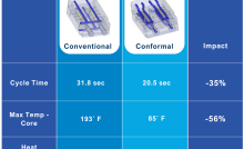
Forget typical cycle times. We're pushing the boundaries of conformal cooling. While traditional approaches deliver…
Forget typical cycle times. We're pushing the boundaries of conformal cooling. While traditional approaches deliver…
From left to right: Brayden Janak (apprentice); Logan Vifaquain (CNC machining, Programming and CMM); Ron…
SyBridge Technologies is proud to announce we have been awarded the 2023 General Motors Supplier…
Today, designers and engineers are accustomed to working with digital tools in their day-to-day jobs.…
Optimizing Your Injection Molding Process for Cost-Effective Manufacturing Excellence In today’s competitive landscape, manufacturers are…