
This illustrated checklist will help teams understand the basics of designing for manufacturability (DFM) with fused deposition modeling (FDM).
Fused deposition modeling (FDM) is one of the most common forms of additive manufacturing and what most people think of when they hear “3D printing.”
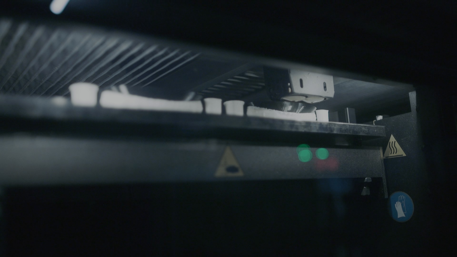
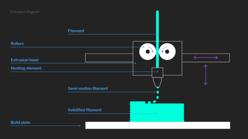
Fused Deposition Modeling Design for Manufacturing Guide How does FDM work? During this process, the FDM machine extrudes heated thermoplastic filament through a nozzle, building up the component one horizontal layer at a time. One significant advantage of the process is how quickly the machines can produce parts in comparison to legacy technologies. Given that turnaround periods can be as short as 24 hours, FDM is a useful process for creating affordable rapid prototypes and even some functional parts.


The convenience of FDM printing and the accessibility of FDM materials has led to the technology’s popularity among both professional and hobby users, who can use the technology to create everything from toys to foods to electronic enclosures. Process innovation for FDM is still ongoing, with new capabilities now including non-planar printing, composite printing, and multi-material printing.
Designing for manufacturability is important for all designers and product teams, regardless of manufacturing technology. Part designs not only need to meet the desired functional and material requirements expected of the prototype or final part, but they also need to take the manufacturing process itself into account.
This guide includes five tips for ensuring that your FDM-printed parts are high quality and efficient to produce. Double-checking your designs against this list before submitting them for manufacturing can help improve your part, save time and resources, and speed up production times.
Due to how FDM printers extrude lines of thermoplastic material one layer at a time, the process is inherently anisotropic, which means the part’s bulk mechanical properties vary along different directions. This stems from the fact that the bond strength between layers is different from in-plane strength. FDM-printed parts offer the highest tensile strength parallel to the path of the print head (within the X-Y, or slice, plane). The bond strength between layers will affect the tensile strength of the Z-direction, which will typically be less than tensile strength within the X-Y plane.
FDM is not recommended for producing critical mechanical components, as thermoplastics are susceptible to material creep if placed under high stress for long periods of time. A part’s build orientation and geometry can be modified to account for or mitigate this. Likewise, incorporating chamfered and rounded edges into your parts and tooling will improve their longevity and reduce stress concentrations.
Product teams should know that the FDM process cannot achieve extremely tight tolerances.
Most industrial FDM machines can provide dimensional accuracy of ± 0.15% (lower limit ± 0.2mm) and desktop printers can achieve tolerances of ± 0.5% (lower limit ± 0.5mm). However, because FDM involves large amounts of heat, other factors like geometry will impact the accuracy of the printed piece as it cools. If a part requires critical surfaces or high-tolerance holes with greater accuracy than the FDM printer can achieve directly, then consider post-processing operations or adding components such as bushings and threaded inserts. Often, FDM tolerance issues can be reduced through further post-processing.
When it comes to text size, the minimum suggested size for in-plane text is 6mm boldface, but the actual values will vary by printer. Text on vertical walls can be as small as 3.5mm boldface.
If your part contains thin gaps, they should maintain a minimum width of 5mm to guarantee that the support material can be easily removed. Orienting the part build so that gaps are perpendicular to the X-Y plane helps to ensure that a good surface finish is maintained.
The optimum wall thickness for your part will be determined by the size of the filament. Generally, features that are two times the thickness of the filament or thinner do not print well. For walls, four times the filament thickness is adequate.
Closed, in-plane profiles tend to print very well with FDM as closed loops allow fast and seamless printing. Examples of this would include vases, cups, and tubes, rather than complex parts with discontinuous sides and sharp features. While not necessary to achieve a nice part, designing with this in mind can help ensure successful FDM prints.
Holes created through FDM printing should have a diameter no smaller than 1mm in order to ensure the feature resolves well. As with gaps, orienting holes to print perpendicular to the X-Y plane can improve feature quality. Drilling out or reaming holes during postprocessing is another method of ensuring accuracy.
Since FDM builds the part layer-by-layer, if overhangs in the part are large enough, there will not be enough support to hold the new material up off the build plate. This material must either be supported in the printing software with sacrificial support geometry or the part must be modified to eliminate the overhangs.
Warping occurs during the cooling process when different sections of the piece solidify and shrink at different speeds, creating internal stresses that pull the material in a way that is non-uniform. While warp isn’t a problem for all FDM-printed parts, certain design features like vertical walls, thin sections, or features with high aspect ratios can increase the likelihood of a part developing warp during the cooling process.
Warp can be avoided by:
Sectioning simply means dividing your part’s CAD file into small, separately printed components. Sectioning makes it possible to build and assemble parts that are too big for the printer’s build volume or to reduce the need for support structures. Printing fragile features separately can also allow you to use a better-suited build orientation, thereby producing a stronger, superior part. Sectioning parts requires some expertise and care, though, as any time a part is being cut into pieces.
FDM can be a very efficient and affordable method for producing thermoplastic prototypes and parts. Between the short lead times, the availability of the printing technology, and wide material compatibility, it’s no wonder that hobbyists and professionals alike are looking to leverage the benefits of FDM.
When you partner with an experienced manufacturer like SyBridge Technologies, you can be sure that each of these considerations — and many more — will be taken into account. Our team of engineers and product managers leverage cutting-edge digital design technologies and decades of experience to ensure that each and every part we produce is the best possible part for the job. Not only that, our team works closely with customers during each step, from design through fulfillment, to ensure that each part is optimized for end-use and manufacturability.
Contact us today to learn more about how we can make your ideas a reality.
Forget typical cycle times. We're pushing the boundaries of conformal cooling. While traditional approaches deliver…
Forget typical cycle times. We're pushing the boundaries of conformal cooling. While traditional approaches deliver…
From left to right: Brayden Janak (apprentice); Logan Vifaquain (CNC machining, Programming and CMM); Ron…
SyBridge Technologies is proud to announce we have been awarded the 2023 General Motors Supplier…
Today, designers and engineers are accustomed to working with digital tools in their day-to-day jobs.…
Optimizing Your Injection Molding Process for Cost-Effective Manufacturing Excellence In today’s competitive landscape, manufacturers are…