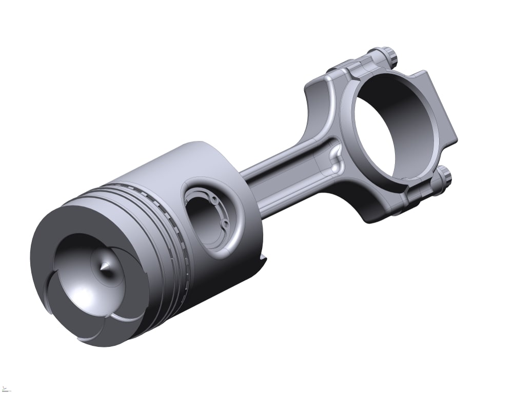

Originally published on fastradius.com on February 21, 2022
Whether you’re manufacturing parts for motorcycles or rebar-tying robots, you’ll need to start with a computer-aided design (CAD) file. These digital files contain 3D designs and other material, texture, and tolerance data to help product teams accurately plan, visualize, and manufacture the final product.
You have plenty of options when it’s time to export your CAD model, but different file formats are best-suited for different use-cases. Let’s take a look at STEP files, how they’re used, and their advantages and disadvantages so you can determine whether or not the STEP file format is the best fit for your project.
Since other formats may require you to take intermediate conversion steps, STEP files (.step) were created to simplify saving and sharing three-dimensional models across CAD systems. STEP files go by many names including ISO 10303, STP, and P21, but STEP is actually an abbreviation for Standard for the Exchange of Product Data. The STEP file image format was developed in the mid-1980s by the International Organization for Standardization’s (ISO) TC 184, and the first edition of STEP came into use in 1994.
Every 3D STEP file contains three-dimensional model data stored in the widely recognized ASCII text code format. While some other file formats only represent basic geometries, STEP files will read and save a 3D model’s entire body with a high level of precision, allowing for more accurate file sharing and opening. Plus, since STEP files are plain text that appears as 3D models when opened in CAD programs, editing STEP files is simple. Likewise, it’s easy to view a STEP file’s creation date, original file name, application origin, and other metadata.


STEP files are commonly used in 3D modeling and architectural design due to their accuracy, cross-platform compatibility, and ability to create detailed models. Also, if you plan on CNC machining or injection molding a part, you’ll need to use STEP files because this file format enables machine tool path calculations.
As one of the most popular neutral CAD formats, the STEP file format is compatible with countless programs. You can use STEP files with Autodesk Fusion 360, Dassault Systemes CATIA, FreeCAD, IMSI TurboCAD, SolidWorks, ArchiCAD, and more, making collaboration easy. Opening and editing files created in a newer software version in an older version — also known as downward compatibility — is also easy with STEP files, as they serve as intermediate links.
Another benefit of using a 3D STEP file format is that your file will store data using a non-uniform rational basis spline (NURBS). Using this mathematical representation of curves and basis splines (B-splines) results in greater flexibility, high dimensional accuracy, and smooth curves on the final product that would be impossible to achieve using triangle or polygon representations. That’s why many designers use STEP files for car bodies and other applications that require extreme precision and high levels of detail.
Since STEP files save the model as an entire body, you can customize and edit your models without losing any quality — even after exporting or re-uploading them. Plus, files in the STEP file format compress far more than source files, even though they’re around the same size. A compressed STEP file is typically 20% the size of a compressed source file, making STEP files better suited for sharing over the internet.
STEP files have a lot to offer, but they do have some drawbacks. For example, STEP files aren’t particularly storage efficient and will take up more space than other 3D model formats. They also don’t contain parametric intelligence; feature history; or camera, texture, material, and light data. Additionally, STEP files have an order set of procedural calls that reference other previously specified procedural calls, meaning it takes a lot of time and effort to create STEP files.
Unfortunately, you also can’t directly render STEP files with a graphics processing unit (GPU), and most renderers aren’t capable of loading STEP 3D files because of NURBS. Instead, you’ll need to convert your model into a series of small triangles for rendering using a software program.
STEP files and STL files are two of the most common file formats, but they each have their own characteristics. STL files only describe a model’s exterior geometry and simplify its features into a mesh made of triangles that’s free of gaps and overlaps, but STEP files save models as single entities and use NURBS, allowing for higher dimensional accuracy and smoother curves. As a result, STL files are lighter, simpler, and more storage-efficient than STEP files.
STEP files are better suited for when you need an extremely accurate model, have a curved part, or are injection molding or CNC machining parts. They are also easier than STL files to customize and edit after being exported, so if you’re planning to do lots of editing or collaborating, you may want to consider using STEP files. If you’re making a 3D-printed prototype, don’t need a high-fidelity product, don’t plan on making edits, or only have flat surfaces, you can use an STL file.
Luckily, you can convert a STEP file to STL by opening your file in the program you used to create it and exporting it as a different file type. At SyBridge, we convert STEP files to STL files whenever we need to 3D print a part.
Many professionals in the manufacturing industry use the STEP file format because of its compatibility across programs and its ability to accurately represent curved surfaces. However, STEP files can be complex and aren’t necessarily the best option for every project. If you need help deciding which file format you should choose, work with a manufacturing partner like SyBridge.
Partnering with SyBridge gives you access to a team of qualified engineers who can answer questions and help you with every aspect of the manufacturing process, whether you need assistance with your design or advice on production. Contact us today to get started.
Forget typical cycle times. We're pushing the boundaries of conformal cooling. While traditional approaches deliver…
Forget typical cycle times. We're pushing the boundaries of conformal cooling. While traditional approaches deliver…
From left to right: Brayden Janak (apprentice); Logan Vifaquain (CNC machining, Programming and CMM); Ron…
SyBridge Technologies is proud to announce we have been awarded the 2023 General Motors Supplier…
Today, designers and engineers are accustomed to working with digital tools in their day-to-day jobs.…
Optimizing Your Injection Molding Process for Cost-Effective Manufacturing Excellence In today’s competitive landscape, manufacturers are…